When reading Shapefiles (SHP) which include terrain Contour lines, it is very common to find that the Z coordinate of each Contour is set as being a numerical data in a Field of the associated data table
Object Elevations in AutoCAD
The change of the Elevation of 2D Objects in AutoCAD allows you to place them in a given Z position. When this value is other than zero, the Objects are moved from the XY base plane to a parallel plane located on another Z position
The result is the same as a vertical displacement for the Objects
Import Z-Contours from a Shapefile
Contour lines are one of several common methods used to denote elevation or altitude and depth on maps. From these contours, a sense of the general terrain can be determined. They are used in a variety of scales, from large-scale engineering drawings and architectural plans, through topographic maps and bathymetric charts, up to continental-scale maps
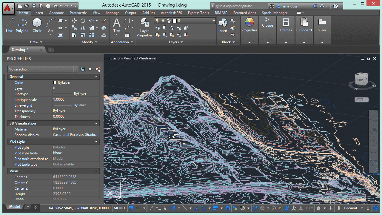
By applying different Elevations to the flat Polylines which define the altimetry Contour lines of a terrain, you can get a pseudo-3D drawing of the terrain that allows you to display it from different points of view in AutoCAD
In addition, there are multiple applications for AutoCAD that allow you to get a digital terrain model (DTM), as well as many other interesting information results for landscaping, civil engineering or urban design, starting from the Contour lines placed on their Z-coordinate
Spatial Manager™ for AutoCAD allows you to set many parameters when importing objects from Shapefiles, or from many other types of spatial files and data sources. One of these parameters defines the Elevations of the imported Objects by reading them from the numeric value in a Field of the associated data table
Please, watch this video to learn how to import Z-Contours from a Shapefile into AutoCAD: