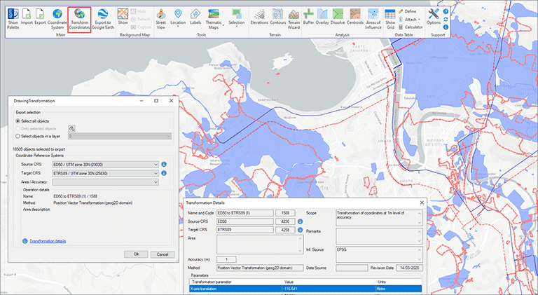
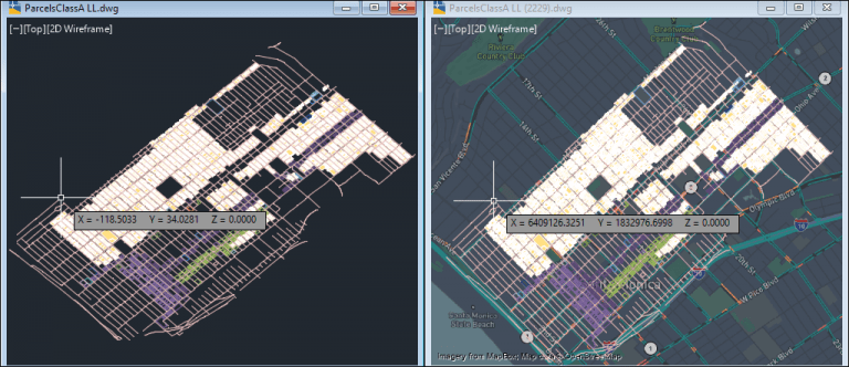
The functionality of transforming the coordinate system (CRS) of a drawing in ONE STEP is one of the tools most requested by the application users. This operation, which in some cases presents a high geometric complexity, is totally transparent and provides a transformed copy of the drawing without losing any of its properties
Related videos: AutoCAD / BricsCAD / ZWCAD
Although it is true that in some cases it was possible to approach a transformation of the drawing’s coordinate system by means of export/import processes, or by means of some external tool, the data structures and properties of a DWG file are very different from those of GIS or Map files, so that only approximations could be obtained that in many cases were not valid
In this new function (SPMTRANSFORMCRS) you will find a tool never seen before in CAD applications to carry out these transformations. The user will only have to choose the source CRS (which will be taken by default from the drawing if one is already assigned), the target CRS and, if necessary, the application area
‘Spatial Manager’ will generate a new drawing in which not only the transformed objects will be included keeping their typology (you can choose to transform the whole drawing or only a part of the objects), but also their visual properties (Layer, Color, Hatch Patterns, Line Types, etc.), Attached Data, relative positions between objects as well as styles of Layers, Texts, Dimensions, etc. That is, a “clone” of your drawing located, scaled, distorted, rotated, etc. geometrically according to the transformation of the coordinate system
In the first part of the above videos you can review the transformation of a drawing between two projected UTM coordinate systems that are based on different ellipsoids and datums. As you may see, while setting up the transformation you can access extended information about the source and target CRSs, as well as the transformation parameters that will be applied in this case. At the end of the video, the two drawings are overlapped (using an XRef) to check the differences in the representation of the geographical objects in the two CRSs
But you can not only perform transformations between projected coordinate systems but also between different types. As you can see in the second part of the video, a transformation of the drawing is done between a 2D Geographic system, whose “coordinates” are Latitudes and Longitudes, to a Projected system whose units are “feet” on which you can carry out real measurements, show Background Maps, etc.
Learn more about Transforming drawings CRS functionality in the ‘Spatial Manager’ technical Wiki:
Notes:
- The Transformations of the drawings CRS are available in the Professional edition of the CAD versions only
- In ‘Spatial Manager Desktop’ this transformation tool is not necessary because as the Map and Layer CRS configuration is managed, the information is always updated when the Map CRS is changed


